Posts

Showing posts from 2020

Race Report - The Dark Dart Dash

 Saturday evening was the biggest test of the equipment so far. Two hundred plus entries, many waves, and four distances. It's probably fair to say I had a fair few nerves going into this. Not on the hardware side, I'd done enough tests on that to be confident, but how easy was the software going to be to use in the field (spoiler - not very). Here's the summary. Good things 100% reliability on hardware All chips read without mis-scans All data transferred correctly Problems  ( and solutions ) - 4 chips were out of sequential order on the master reference sheet causing mixups  - going to rescan everything Web-side software was too complex meaning too long to implement changes  - modifying this (easy job) Used numerical, rather than plain text waves  - will use plain text next time The UID strings do not look correct - this a technical issue. Whilst the UIDs are reported in byte strings and are correct (and unique).  - going to recode to carry out bytearray to hex conversion

Challenges and decisions ahead!

Image
 So, a few weeks ago Pycom announced this- Aside from the implications this has for the case (eeeek!!!!) this may have positive ramifications. Firstly, it looks like an RTC will be onboard. Secondly (and I'm really hoping) the tetchy (technical term) IO expander will be sorted. Thirdly, we could change up a gear and fit the more powerful PN532 NFC reader. There's already a circuit python library available so it won't take much to adapt it to micropython. Watch this space.... I really hope it fits in the current casing though....

Mesh networking works!

 So, one of the key features I wanted to implement in this project was mesh networking. Pycom have their own implementation of it, called Pymesh, so I figured it would be ok. One look at the docs was quite confusing for a novice like me, however on closer inspection it was integrated in the Pybytes (Pycom's online dashboard/gateway). I am already using the release feature in Pybytes to push code to the devices over wifi, which means the USB post does not need to be accessible, so using Pymesh that way made sense. The benefits of Pymesh- Mesh networking over LoRa Self healing Allows cheaper no LTE devices to be easily incorporated The downsides of Pymesh- Not sure if I can use the things network at the same time - need to check this! Longer boot time Greater load on the microcontroller processing capacity

Getting Organised

Image
 So after finishing prototype one and two, it was apparent some internal organisation was needed. Whenever the case open and closed, care was needed to stop wires getting caught in the hinge. Now obviously I could do a much neater job with a ribbon cable, but that's very fiddly and I don't have ribbon cables to hand. But I do have cable ties, and they did the job. Very annoyingly the switch on the final device (ironically Timer001) is soldered the opposite way to the other two. My fault but still annoying and I didn't realise until the switch was glued in. Also, this was the first time I used hot glue to reinforce the connections. it doesn't seem to have caused any issues so I'll make it feature of the rest. Pycom have also said they will be releasing a new LTE antenna soon, which should have greater gain than the current antenna, which is positive. In other news, the three prototypes now have their own flightcase, which is great! 

Like blu-tac, only stronger

Image
 A brief update - following my left arm being rendered useless for a short period of time I now have some use coming back to it. Not full range and definitely nowhere near full strength, but enough to support bits and pieces, hold solder etc. Which means I've had chance to test out my new glue -  JB PlasticWeld Epoxy Putty - and it's great*! It comes in a tube, you cut of an amount (not much is required) mix between your fingers until a uniform consistency and colour is achieved, and then mould into the required shape. I used it to create mounts for the standoffs (new shorter ones - see the next post) on the ABS casing. Something standard epoxy just hadn't done well. To make sure they held, I coated them in PlasticWeld Epoxy .  You can see the standoffs in the photo below, just to the left of the power switch- *I'm not being sponsored for this and am in no way connected with JB Weld, their product just did what I needed to, really well 

New code release shortly, plus glue!

Firstly the seemingly random restarts are solved, and will be pushed to github later. A shared function and a shared list between the threads were to blame. Had 12 hours uptime without wavering. I'll make it a new point release. Pybytes also starts on boot so in that respect it is pymesh compatible. However, the code isn't fully pymesh compatible, yet.  Secondly, gluing the devices together has been an utter pain. With standard epoxy and super glue both failing frequently to adhere to the abs casing. To counter this I've bought some JB Weld plastic weld two part liquid epoxy and two part putty. Both list as being effective on abs and ideal for attaching metal to plastic. We'll see! The hitch in development is now my arm, or more specifically my elbow. As a result of an unscheduled meeting with a van whilst I was cycling home from the day job, my elbow is in a few more bits than it's supposed to be. One handed gluing with two part, one handed soldering, one handed wo

First real life test!

Image
I can tell the day job has started again, development work has been somewhat on hold. However, it was race day on Saturday! Which meant registration duties for me. And the system has had it's first real life test! Wild Running very kindly volunteered their Race With No Name ultra to use it. It was a small race due to covid restrictions, so very easily manually timed if the system failed. The race was brilliant, and the system worked. However, it has generated a job list- The PCB header pins used to connect the RTC to the Pycom Pyscan are too long, meaning the chance of a short with either the RTC of the prototype board holding the LED and buzzer is too great. Temporarily solved with some hastily attached plastic, but a better solution is required. Did get the odd, weird restart in first 30 mins of operation. This is manageable for a race this small - but not acceptable. Digging into this further. The IP rated aerial connectors come loose. Going to use the standard ones instead and

Overlooking the amps

Image
Sorry for the lack of recent updates - back on the day job now which limits the time I spend building timing gear. There's a scene in one of my favourite films, Apollo 13, where the engineer John Arron highlights that the battery capacity is one of , if not the, main limiting factor on the crew's survival. Now, whilst the situation in scene is considerably more critical than in a timing device, the principle is the same. Electricity is everything. For about a month I've been chasing errors, particularly when using LTE, which have been causing unexpected restarts or loss of communication.  The culprit, it turns out was the power supply. Now I'm not 100% sure how the Pycom board is wired, but essentially the LTE modem / wifi connection pulls from the 3.7v nominal LiIon connection. Which only charges from usb at a rate of 100mA (the battery was 1000mAh). The modem and wifi are known to cause a current spike when transmitting. Net result, very quickly I was getting errors s

It works!

Image
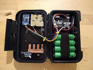
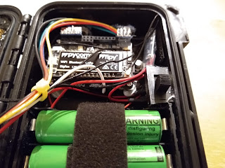
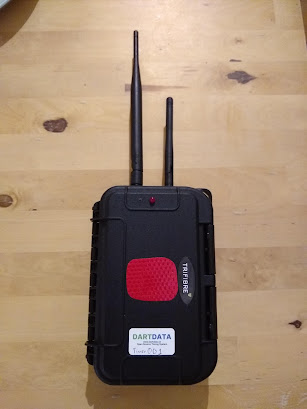
 Prototype 1 is built! Perhaps more surprisingly, it worked first time.... Anyway below are some pictures and notes. Next up is prototype 2 and 3. The cable tie clips will be changing position on these ones and some cable routing may vary. I've also discovered that epoxy resin + the "max" cases I bought doesn't lead to a good bond, hence a lot of superglue was used. So on the first photo the most striking feature is the reflective red patch (cut in a hurry I know). This indicates where to scan the NFC chip as the molex antenna is on the inside of the case in this location. LoRa antenna on the left, wifi on the right. The wifi external antenna has be enabled in the boot.py script (see the github site for code ). The buzzer (well the hole for it) and LED are visible.  Inside is much more complex. Here's what we can see, left to right, top to bottom- An adafruit 1/4 breadboard perma-proto which holds the circuit for the buzzer and LED RTC module communicating via i2

Why build / use the Dart Data system?

 The idea for Dart Data initially came out of a weekend when I timed and ran comms for an ultra distance event that went really really badly. The saving grace in the event was the GPS trackers, as it allowed several small situations from becoming critical. This coupled with my experience of being asked at every race I timed, "where is X?", "is X on the right route?" and similar, meant I was looking for a way of bringing the benefits of GPS tracking to shorter events, or events that could not afford GPS trackers. I was already running RFID and NFC timing options using Webscorer  as the driving software. I liked and still like Webscorer. However, there are situations when it's handy for multiple people, on multiple devices, to edit competitor details. Here's a list of the features of the Dart Data system, and why they were chosen- Long battery life - for long races! Cloud based reporting (google sheets) - allows multiple people to see and, if necessary, edit

Dart Data vs RFID vs other NFC (webscorer) vs SPORTident

Image
 The Dart Data system was produced as a response to race which did not go so well, and as a response to a growing dissatisfaction that there was no system out there which exactly met the needs for some of the vents I was timing. This does not mean it's the best approach for all events! Below is a table highlighting some of the strengths and weaknesses of four different systems. The Dart Data NFC based system Other NFC based solutions - for example Webscorer RFID based timing - again using Webscorer as the example The SPORTident system, a classic staple I still use the systems other than Dart  Data for events, and all have their place in different situations. For example, SPORTident would be the wrong call for a road cycling time-trial, but would be spot on for a 30 checkpoint pro-orienteering event.

Prototype time

Image
 So with a fully working proof of concept it's prototype building time. There's still a few tests to run (see the bottom of this post), but the results impact software, not hardware. It's time to build. Currently I only have the parts (due to finances) to build three. I want to build a minimum of eight ideally to prove this system's effectiveness in complex orienteering and staged situations. You'll notice in the bottom right the remains of Anker battery pack - this was taken to pieces to reduce it's size. It was effective. The circuit with the transistor is in the top left, next the the external RTC. This positioning allows more space around the Pyscan and FiPy for connections to power and the mounting of a small Li-Ion. Why use the disassembled Anker and not a larger Li-Ion? Principally cost, but also it allows 5v to be taken off for the buzzer and LED circuit. All that's left to do is the final power circuitry (mainly the switch) and mounting the FiPy. He

Commeth the hour, commeth the right resistor

Image
 So I've spent some considerable time rebuilding the proof of concept (or developer kit). The old system, mounted in a small box, with a breadboard hanging out and looking dangerously close to my old GCSE systems and control project, was too prone to errors developing due to a loose wire or similar (much like the GCSE project). I have also been troubleshooting a (now resolved) issue with the buzzer and LED, more on this later. With the use of a lot of epoxy resin, the development kit now looks like the pictures below. Everything secure in it's place. It's makes it a lot clearer to explain too. In the prototypes, there will only be one switch to control both USB and li-ion power. The breakouts from the pins on the underside of the Pycom Pyscan can clearly be seen. Buzzer and LED issue For weeks I have been wrestling with inconsistent results with the buzzer and LED. It boils down to current issues. There is a GPIO extender on the Pycom Pyscan board, but either an issue with

Board Selection

Image
When I was first working out if I could timing better and safer by building my own system, I spent ages making decision, then remaking them over which board to base it around. It had to run python (because I know python the best), have low power consumption, be able to attach storage, be bale to either scan NFC chips or attach an I2C scanner, and multiple communication options. My go to was the Raspberry Pi Zero. I've lots of experience with these in robotics, and they're great pieces of kit. However, connectivity and power consumption was an issue. This was initially my preferred choice, and I may well revisit it in the future. This time round though I bypassed it, whilst the board is cheap, it would require external RTC, power management (raspberry pis + uncontrolled power loss = lost data), NFC scanning and communication (which would have to be a USB 4G dongle to keep costs down). These all add up in terms of complexity (wires to come loose), power requirement and money. The

Timing conundrum

So in my spare time (when I'm not teaching) I do timing and race control with Wild Running (https://www.wildrunning.co.uk/). This involves a mix of short races, swim runs and long ultras.  In the past the timing split has been a bit like this - Shorter runs - borrowed RFID (volume over line in a short space of time) Swim Run - hired sportident (the competitors like splits) Long runs - GPS and manual via webscorer (GPS checkpoints, manual finish) However, I'm now helping time events where the results rely on accurate checkpoint timing and safety demands either real time tracking of checking people in and out. The later requires a lot of people (or live updating sportident gear - elusive and expensive) and can be thrown by marshals having to respond to first aid etc. The former is expensive. So I'm starting development on a new system.  This new system will allow live checkpoint tracking, will need to be weatherproof and robust. A long battery life is a must, as is ease of us