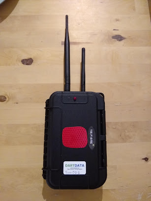
It works!
Prototype 1 is built! Perhaps more surprisingly, it worked first time.... Anyway below are some pictures and notes. Next up is prototype 2 and 3. The cable tie clips will be changing position on these ones and some cable routing may vary. I've also discovered that epoxy resin + the "max" cases I bought doesn't lead to a good bond, hence a lot of superglue was used.
So on the first photo the most striking feature is the reflective red patch (cut in a hurry I know). This indicates where to scan the NFC chip as the molex antenna is on the inside of the case in this location. LoRa antenna on the left, wifi on the right. The wifi external antenna has be enabled in the boot.py script (see the github site for code). The buzzer (well the hole for it) and LED are visible.
Inside is much more complex. Here's what we can see, left to right, top to bottom-
- An adafruit 1/4 breadboard perma-proto which holds the circuit for the buzzer and LED
- RTC module communicating via i2c and powered from the Pycom Pyscan
- A molex NFC antenna with the required cable soldered to it
- The LTE (NB-IOT) antenna - just the stock one from Pycom
- Antennas mounted to through hole connections sealed with superglue and rubber seals
- A 1000mAh 3.7v li-ion - needed due to extra current draw when transmitting via LTE
- The Pycom Fipy mounted on the Pycom Pyscan. Standoffs epoxyed into the case to allow the devices to be unscrewed. i2c connections and pin connections (for the buzzer, LED and RTC) are either soldered direct to the board or to stipboard, allowing headers to be soldered and then connected - I'm going to film a build video for the next two which should make it easier to follow what I'm trying to describe.
- The bottom third or so of the case on the right is a dissembled Anker 10,000mAh power bank. I've been doing a lot of pondering on the power supply recently which I'll put up in a post shortly


Comments
Post a Comment