Posts

Showing posts from August, 2020

It works!

Image
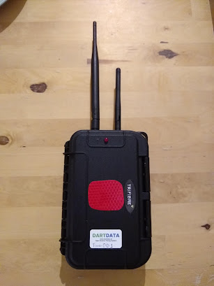
 Prototype 1 is built! Perhaps more surprisingly, it worked first time.... Anyway below are some pictures and notes. Next up is prototype 2 and 3. The cable tie clips will be changing position on these ones and some cable routing may vary. I've also discovered that epoxy resin + the "max" cases I bought doesn't lead to a good bond, hence a lot of superglue was used. So on the first photo the most striking feature is the reflective red patch (cut in a hurry I know). This indicates where to scan the NFC chip as the molex antenna is on the inside of the case in this location. LoRa antenna on the left, wifi on the right. The wifi external antenna has be enabled in the boot.py script (see the github site for code ). The buzzer (well the hole for it) and LED are visible.  Inside is much more complex. Here's what we can see, left to right, top to bottom- An adafruit 1/4 breadboard perma-proto which holds the circuit for the buzzer and LED RTC module communicating via i2

Why build / use the Dart Data system?

 The idea for Dart Data initially came out of a weekend when I timed and ran comms for an ultra distance event that went really really badly. The saving grace in the event was the GPS trackers, as it allowed several small situations from becoming critical. This coupled with my experience of being asked at every race I timed, "where is X?", "is X on the right route?" and similar, meant I was looking for a way of bringing the benefits of GPS tracking to shorter events, or events that could not afford GPS trackers. I was already running RFID and NFC timing options using Webscorer  as the driving software. I liked and still like Webscorer. However, there are situations when it's handy for multiple people, on multiple devices, to edit competitor details. Here's a list of the features of the Dart Data system, and why they were chosen- Long battery life - for long races! Cloud based reporting (google sheets) - allows multiple people to see and, if necessary, edit

Dart Data vs RFID vs other NFC (webscorer) vs SPORTident

Image
 The Dart Data system was produced as a response to race which did not go so well, and as a response to a growing dissatisfaction that there was no system out there which exactly met the needs for some of the vents I was timing. This does not mean it's the best approach for all events! Below is a table highlighting some of the strengths and weaknesses of four different systems. The Dart Data NFC based system Other NFC based solutions - for example Webscorer RFID based timing - again using Webscorer as the example The SPORTident system, a classic staple I still use the systems other than Dart  Data for events, and all have their place in different situations. For example, SPORTident would be the wrong call for a road cycling time-trial, but would be spot on for a 30 checkpoint pro-orienteering event.

Prototype time

Image
 So with a fully working proof of concept it's prototype building time. There's still a few tests to run (see the bottom of this post), but the results impact software, not hardware. It's time to build. Currently I only have the parts (due to finances) to build three. I want to build a minimum of eight ideally to prove this system's effectiveness in complex orienteering and staged situations. You'll notice in the bottom right the remains of Anker battery pack - this was taken to pieces to reduce it's size. It was effective. The circuit with the transistor is in the top left, next the the external RTC. This positioning allows more space around the Pyscan and FiPy for connections to power and the mounting of a small Li-Ion. Why use the disassembled Anker and not a larger Li-Ion? Principally cost, but also it allows 5v to be taken off for the buzzer and LED circuit. All that's left to do is the final power circuitry (mainly the switch) and mounting the FiPy. He

Commeth the hour, commeth the right resistor

Image
 So I've spent some considerable time rebuilding the proof of concept (or developer kit). The old system, mounted in a small box, with a breadboard hanging out and looking dangerously close to my old GCSE systems and control project, was too prone to errors developing due to a loose wire or similar (much like the GCSE project). I have also been troubleshooting a (now resolved) issue with the buzzer and LED, more on this later. With the use of a lot of epoxy resin, the development kit now looks like the pictures below. Everything secure in it's place. It's makes it a lot clearer to explain too. In the prototypes, there will only be one switch to control both USB and li-ion power. The breakouts from the pins on the underside of the Pycom Pyscan can clearly be seen. Buzzer and LED issue For weeks I have been wrestling with inconsistent results with the buzzer and LED. It boils down to current issues. There is a GPIO extender on the Pycom Pyscan board, but either an issue with

Board Selection

Image
When I was first working out if I could timing better and safer by building my own system, I spent ages making decision, then remaking them over which board to base it around. It had to run python (because I know python the best), have low power consumption, be able to attach storage, be bale to either scan NFC chips or attach an I2C scanner, and multiple communication options. My go to was the Raspberry Pi Zero. I've lots of experience with these in robotics, and they're great pieces of kit. However, connectivity and power consumption was an issue. This was initially my preferred choice, and I may well revisit it in the future. This time round though I bypassed it, whilst the board is cheap, it would require external RTC, power management (raspberry pis + uncontrolled power loss = lost data), NFC scanning and communication (which would have to be a USB 4G dongle to keep costs down). These all add up in terms of complexity (wires to come loose), power requirement and money. The